
A Turing Test for Physical Engineering
Segment 1. Building parts from scratch.
Segment 2. Part modification.
Segment 3. Assembling complex mechanism.
Our AI system passed the Certified SOLIDWORKS Professional exam (CSWP), completing all three segments in a single sitting of approximately three hours. Using Quartz, our CAD software, and SGS-Mk2, our foundation model, the agent works through the exam unassisted[1, 2]: no person tells it which features to use.
To our knowledge, this is the first AI system to pass a professional CAD certification.
The exam gave us a concrete test of an agent’s ability to construct, modify, and assemble parts under a time limit. It also exposed where current models struggle, what makes CAD reasoning expensive, and what remains between passing an exam and doing useful engineering work.
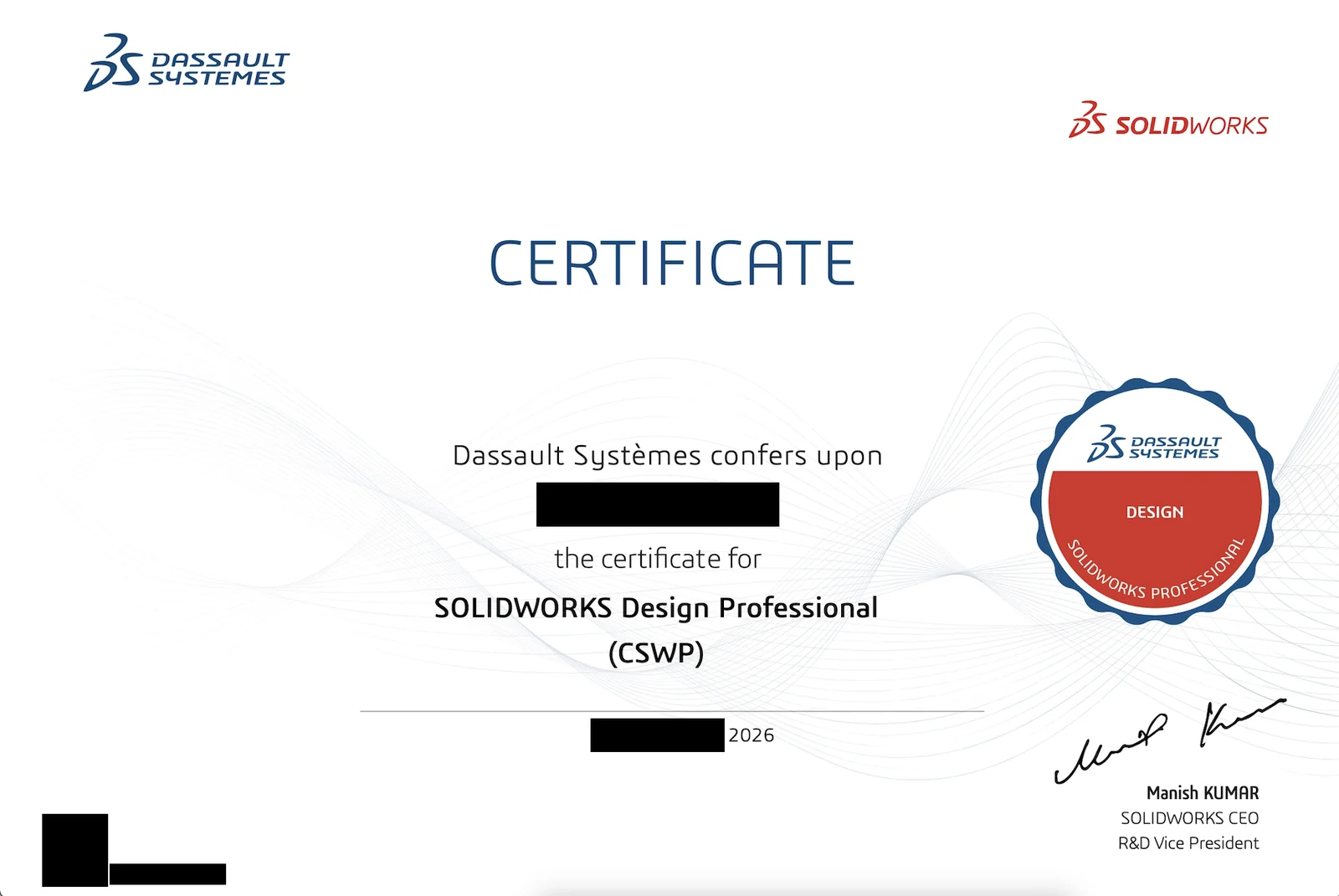
The certification process
Dassault Systèmes offers various professional certifications for engineers who can operate SOLIDWORKS to industry-relevant degrees of sophistication. The Certified SOLIDWORKS Associate (CSWA) and Certified SOLIDWORKS Professional (CSWP) exams constitute some of the better-known examples. Multiple members of the Spectral team are CSWA- or CSWP-certified.
The CSWA has a sitting time of 3 hours, and CSWP is 3 hours 20 minutes within 3 parts. Both sets of questions cover similar subjects, but CSWP is at a much greater difficulty level and its segments can be taken in separate sittings. These include:
- Segment 1: Part construction from scratch (70 min). Advanced feature operations, patterns, sketch constraints, local coordinate systems.
- Segment 2: Part editing (50 min). Complex modifications of existing parts.
- Segment 3: Assemblies (80 min). Constructing a complex assembly of over 20 parts using advanced mates, and reasoning about construction geometry, mechanisms, collisions and limits of range of motion.
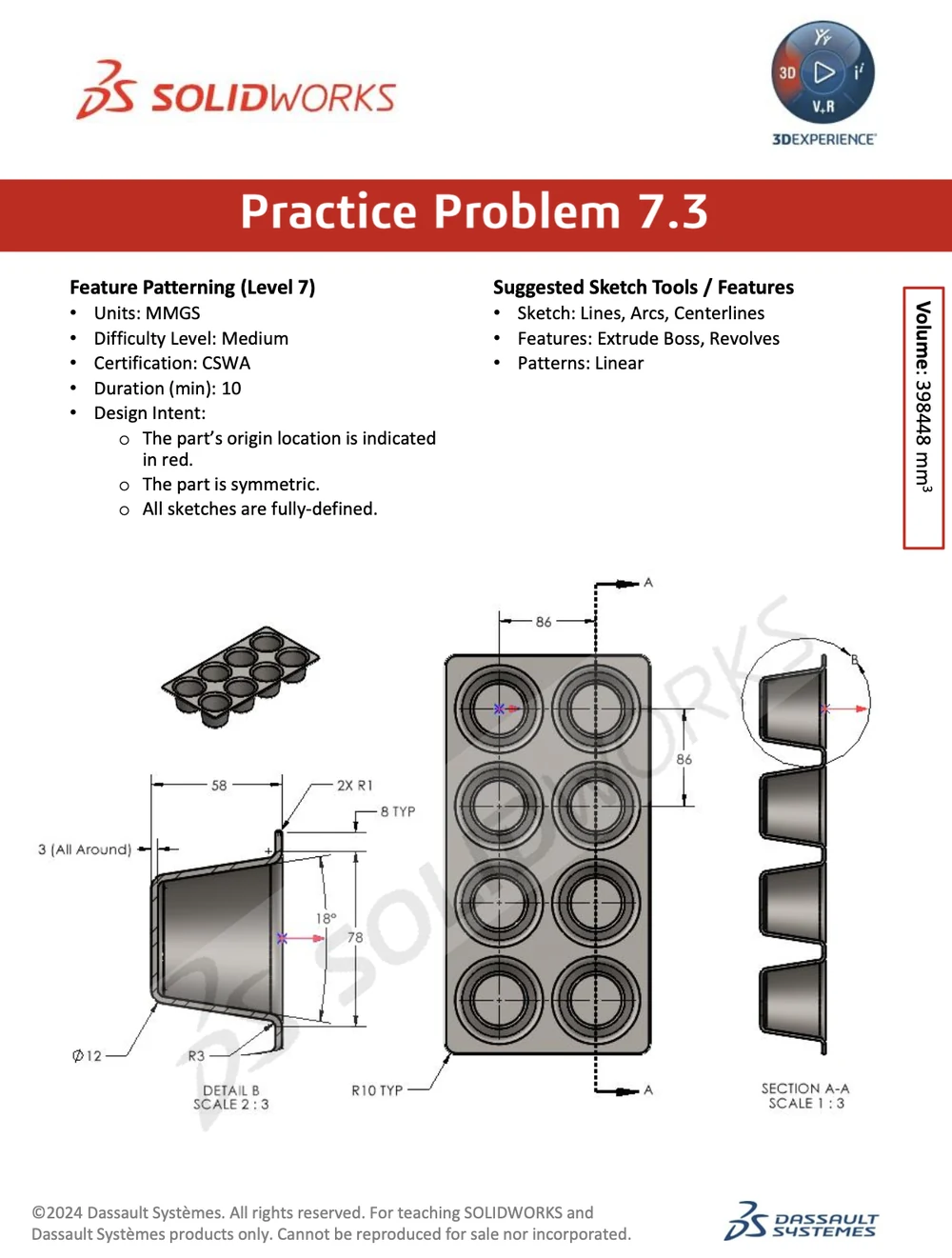
(a) Practice problem 7.3 · Feature patterning. CSWA level, 10 minutes. Model the patterned tray and report its volume.
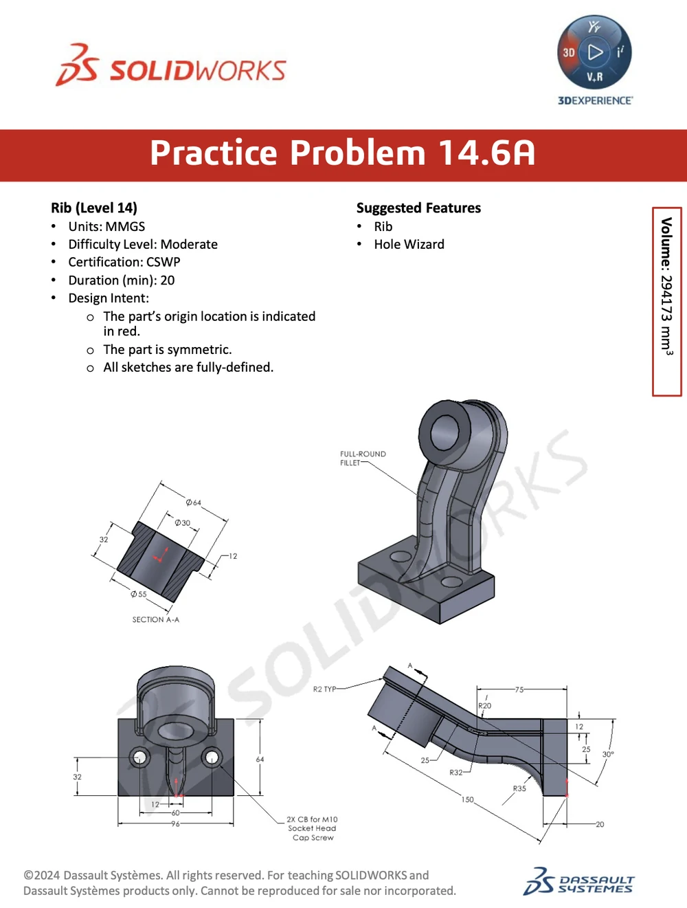
(b) Practice problem 14.6A · Ribs. CSWP level, 20 minutes. Model the ribbed bracket and report its volume.
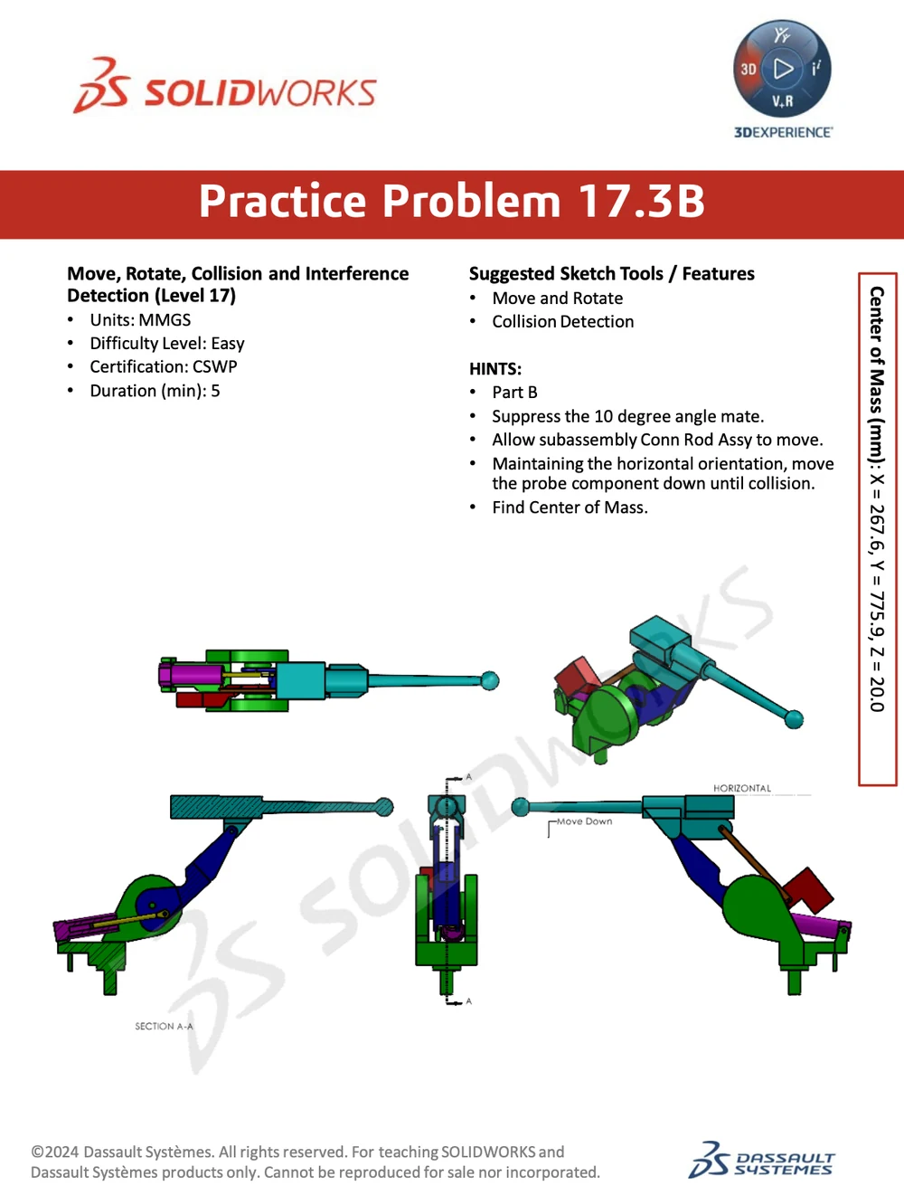
(c) Practice problem 17.3B · Collision detection. CSWP level, 5 minutes. Move the probe down until it collides, then report the assembly’s center of mass.
Questions are either multiple-choice or number entry. They are generally interdependent and require inferring a center of mass position, a distance, or a mass (equivalently, a volume). The numerical tolerance on these answers is understood to be approximately 0.1%. Dassault does not publish it; the figure comes from community reports and our own trial and error.
A cost frontier
SGS-Mk2, the next generation of our CAD foundation model, is lightweight and requires orchestration by a VLM. It is a single set of weights which we condition and call through various tools within Quartz, each tool being defined according to the needs of a given problem stencil. We compared SGS-Mk2 with frontier models on 45 internally prepared CAD problems: 20 inspired by the CSWA and 25 by the CSWP. The CSWP problems covered all three segments: 10 for part modeling, 5 for part editing, and 10 for assemblies. A candidate counted as correct when its volume, center of mass, or distance was within 0.1% of the accepted value.
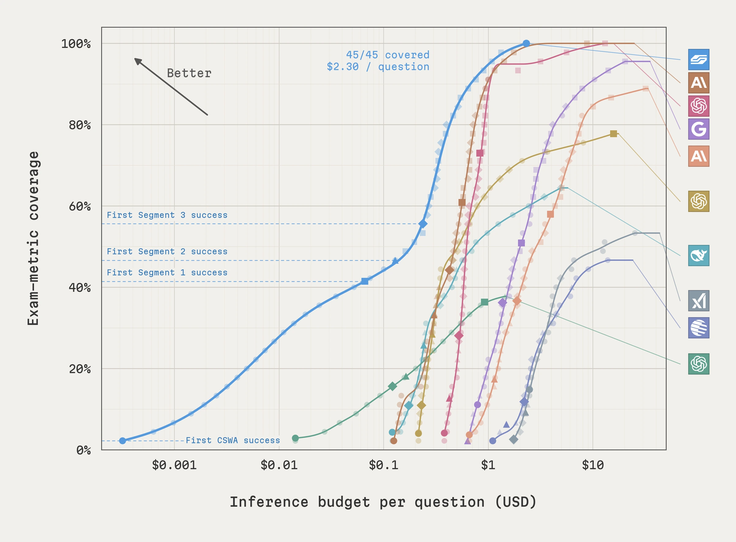
Frontier models did not consistently solve CSWA-like problems at lower cost than CSWP-like ones; some spent more on them. SGS-Mk2 covered most of the CSWA-like problems before its first CSWP-like success, at a few cents per question or less.
We did no exam-specific training. The CSWP itself is not public, but official practice problems and third-party solutions are, so the orchestrator may have seen similar problems during training, as is often the case with similar benchmark announcements[3]. Our 45 emulated problems were prepared by our team internally.
An unfortunate discovery
While navigating Windows APIs to survey the TesterPro environment via our harness, it became apparent that this software, which delivers both the CSWA and CSWP exams, exposes direct access to exam answer keys via an unsecured local SQLite DB backend. Whoops!
Given the nature of this bug and the fact that coding agents have effectively democratized access to system-level APIs[4, 5], this finding unfortunately calls into question TesterPro-based certifications issued in this calendar year. We reported the issue to Dassault Systèmes in advance of this announcement.
This flaw has no bearing on the cost results in Figures 4 and 10. Those experiments ran on our own 45 emulated exam problems inside Quartz, entirely outside TesterPro.
During certification runs, the agent could act only through Quartz’s CAD tools, the SOLIDWORKS COM API, and an answer submission function to TesterPro. It had no shell, file or database access (including code execution functions in the COM API), so the answer store was out of its reach.
Frontier model capabilities
Our agent has passed the live exam many times, though not yet with a perfect score, primarily because the harness times out in Segment 3. The exam also made a useful sandbox for frontier models working inside our CAD harness. As of this writing, frontier models do not consistently pass it single-shot in the allotted time, mostly because of reasoning failures and partly because of the time limit.a One closed-weight frontier model did reliably pass when we ran it as the VLM orchestrator inside our environment, with our tools and moderate prompt engineering. No other model came close for the same spend, and even this one cost about 20 times as much as our human-operator baseline in its best passing run, and over 40 times in its worst. Putting SGS-Mk2 in the loop cut per-problem API requests and cost by between 46% and 87% on problems involving genuine geometric reasoning.b We measured this by replaying the same exam problems, since each live exam presents different questions. However, we believe our results so far are still not the cost floor, and we continue to optimize.
The live exam is a stricter test than our QA experiments, in which two frontier models eventually cover all 45 problems (Figure 4). In QA, a question counts as solved if any one of many sampled candidates is correct. The exam scores the single answer the agent submits, under a time limit, and later questions build on earlier ones.
More generally, frontier models didn’t always reason about geometry when they could simply avoid it using additional context. Some achieved strong performance on the multiple-choice portions of the exam through process-of-elimination reasoning alone. This is not wrong, but represents a shortcut the live exam format allows, and does not carry over to design work, where there is usually no answer to read off. Our QA experiments graded a computed volume, center of mass or distance, so process of elimination wasn’t available.
When frontier models did reason about geometry, they did it inefficiently. Model failures were often specific: selecting the wrong face, omitting a necessary constraint, or spending too much computation exploring possible constructions. These observations shaped where we applied SGS-Mk2 and what we are developing next.
Face, edge, and vertex selection
We noticed that even at high effort settings, reasoning models would flounder in tasks where it was necessary to reason over relationships between faces, edges, and vertices. Models repeatedly confused cardinal directions, such as “rear” versus “front”. They failed at targeting sharp tips. In some cases the likely reason for these mistakes was reasonably apparent, in that single-shot VLM performance is subject to visual-semantic ambiguity: for a face labeled as e.g. the “underside” for a mate, if the model only has orthographic renders without depth shading, it would frequently select the incorrect topological candidate, and would waste valuable exam time reasoning over the options.
These detours often caused timeouts even when frontier models eventually found the correct target, and often they never did. Performance on selection-driven feature operations, especially fillets but including shells, suffered as a result of these behaviors, although for fillets we observed generally small impact on exam-relevant metrics like part volume. Others have noted these observations before for fillets and shells specifically[9], but we see a much broader trend, and we believe solving it requires at minimum endowing models with some native understanding of geometric constraints. Because mates are defined on faces, edges and vertices, these selection errors become mating errors, which in precision engineering and manufacturing are the worst kind: small enough to pass a visual check, and large enough to matter (Figure 6).
Constraint-driven CAD
Frontier reasoning models did not reliably mate parts as a result of their struggling with face, edge, and vertex selection. They also faced challenges in accurately constructing multi-view, dimension-linked parts with mathematically-specified constraints in their drawings. SGS-Mk2 is trained to generate sketch constraints because it allows us to scale toward manufacturing-relevant parametric CAD. But they are also load-bearing in that when we ablated mates from SGS-Mk2 outputs (i.e. instance- and pose-only inference), no amount of resource was sufficient to pass a single Segment 3-like QA question within the 0.1% answer tolerance.
The underlying problem has to do with how CAD software represents physical systems practically, rather than explicitly. A faithful one-to-one digital representation of an engineering system is computationally infeasible, so some degree of simplification is always required. What physics is acceptable to make implicit can be a function of considerations such as the computer a manufacturer decides to purchase. For example, screw threads can easily overwhelm most CAD suites, and they complicate mates because they divide the faces of the screw shaft. Higher-end processors can handle them to a degree, but it’s far easier to simply represent screws as cylinders, especially if they are being procured instead of machined in-house. Similarly, simulating the drying of epoxy or resin is probably not something any engineer wants to spend their time on, when it is far simpler to add mates which annotate the assembly and enforce that the two faces being adhered to one another should be flush in their digital representation.
Nevertheless, mate systems in CAD software are generally hard to build consistently and hard to understand once built. It is not uncommon that engineering firms will use no mates whatsoever in their assemblies. In fact, a workflow to infill missing mate systems in assemblies is something our customers have explicitly and consistently requested. Our team went ahead and built one using SGS-Mk2. Figure 7 shows a case study on a single complex, unmated rotary index table assembly, which you can compare side-by-side with a mate system produced by our team, as well as the best outputs we were able to obtain from frontier models alone in an equivalent amount of time. Passing the frontier models candidate joints from a rule-based kinematic search instead did not help: the assembly came apart as soon as the disc turned. When we pass SGS-Mk2 traces as recommendations to the same frontier models for this assembly, we found they were able to recover all 12 cam-follower joints.
In running this workflow more broadly, we’ve observed that frontier models consistently misinterpret CAD context, especially structural considerations such as screw boreholes. Simulated at face value, assemblies without screws tend to fall apart, but the CAD-correct answer is generally to mate each borehole as if its screw were already in place.
Mates are intended to be annotations of engineering intent: constraints that make sure the system does what it is supposed to do. For users, that isn’t only a convenience but a matter of safety, interpretability, and alignment. At the same time, the design of a part or assembly by itself only accounts for a small portion of the work which goes into designing and manufacturing a real product end-to-end. This fact manifests in subtle ways within CAD contexts. Screws might, for example, overlap solids with their bores because an engineer wishes to express that they be drilled in-place. Another engineer might make a sheet metal part as an assembly of its bent faces, so that mates blur the lines between feature and subassembly trees. Frustrating as these cases might be philosophically, the only meaningful guideline for what makes a CAD workflow acceptable is whether the intent underlying the construction can be suitably and physically realized.
Searching over construction sequences
When generating even simple parts in CAD, there are generally many reorderings of operations which reproduce the same drawing or geometry. The final-state target can be perfectly well-defined, and yet there will nevertheless be a multiplicity of trajectories from an empty CAD stage to the same finished product. Engineers can prefer different such rephrasings for both aesthetic and practical purposes. There is no simple heuristic for when this rephraseability explodes given an arbitrary feature tree, though multiple common cases can be enumerated. Researchers working within seemingly distant domains such as chemistry and molecular design have developed methods for this class of problems on graph data[6, 7, 8]. However, transferring such methods to continuous solid body parameterizations with constraints is a challenging undertaking.
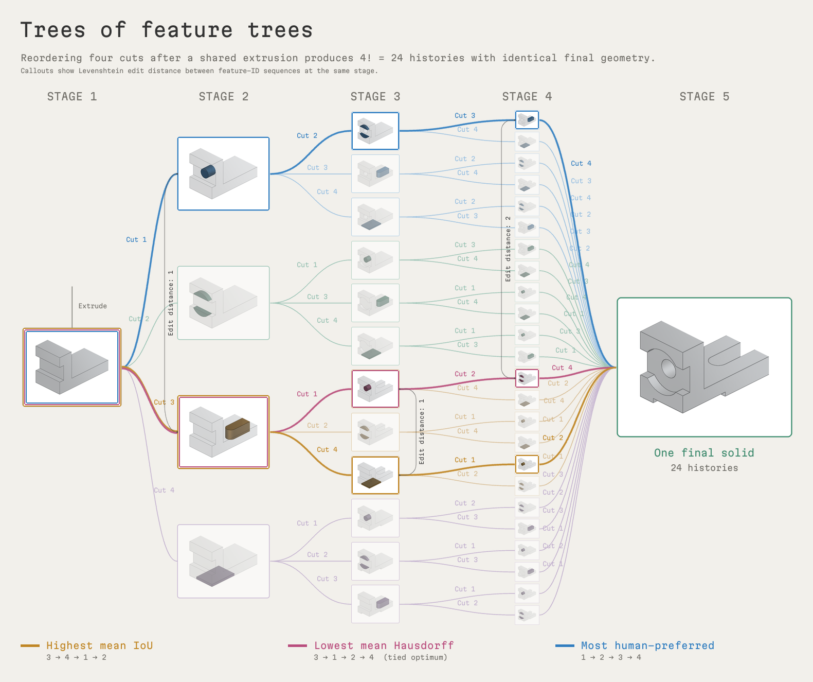
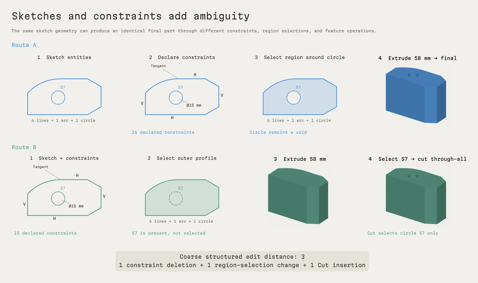
One useful notion of simplicity is how much ambiguity there is in a part’s construction. In our evaluation, we measured variation among each model’s successful feature sequences. Frontier-model costs changed little with that variation: they often spent as much when their successful solutions followed the same sequence as when those solutions differed widely (Figure 10).
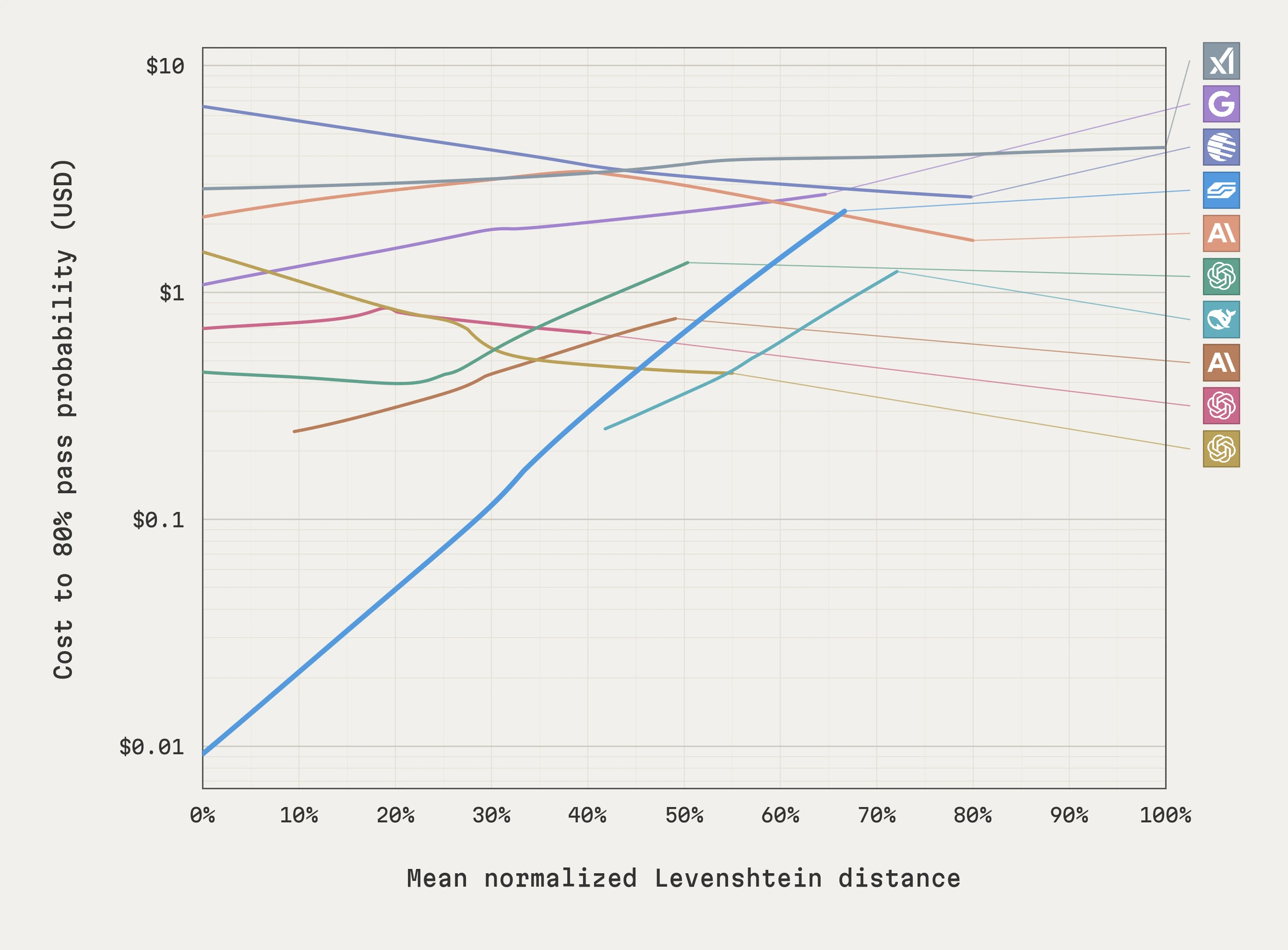
Following this argument through its natural conclusions changes how a CAD agent should search. A looped agent follows a single trajectory, checking its work and retrying until the part comes out right, and pays for general-purpose deliberation whether the part has one sensible construction sequence or dozens. A branched agent samples several trajectories and compares them, so it can spend little where they agree and more where they diverge. SGS-Mk2 was trained under the assumption of branched rather than looped evaluation. It exhibits feature-disperse outcomes while retaining better cost economics than frontier models on the simple parts of CSWA, because it explores more efficiently. As genuine recipe diversity increases, our advantage dissipates and we achieve similar cost economics to frontier models.
Scoring engineering errors
Branching raises a new problem: scoring. Figure 8 already hints at this, because the histories with the highest mean IoU, lowest Hausdorff distance, and highest human preference are three different construction sequences. Shape similarity can also miss errors that matter in engineering. A part may overlap almost perfectly with the reference while missing holes, fillets, or required pattern instances, and standard geometric metrics such as IoU, Chamfer distance and DINO similarity barely move (Figure 11).
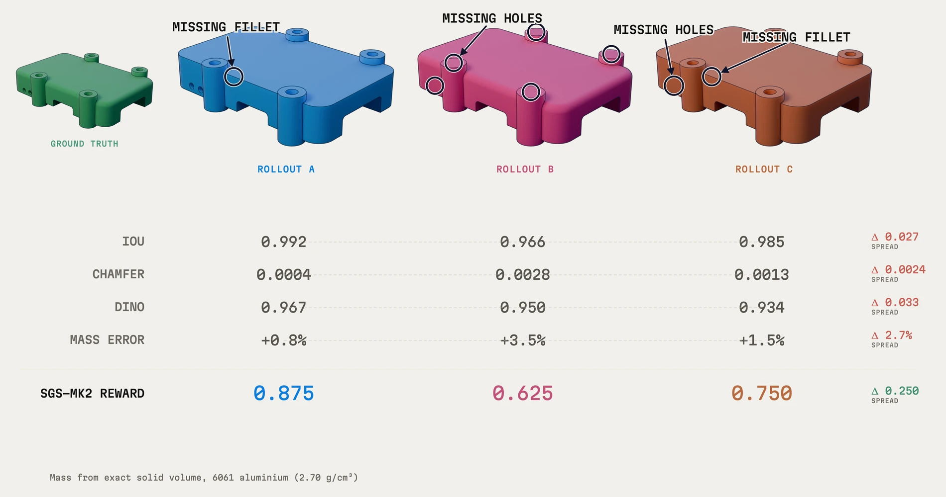
Seeing this variegation, we built our own scoring system to target manufacturability rather than shape alone. It explicitly evaluates the features that decide whether a part can be made as designed, such as pattern counts, hole types, slot shapes and fillets (Figure 12), and gives partial credit to constructions that can be corrected with a small edit (Figure 13). The distinction works in both directions. A missing hole may barely change a geometric metric while making the part incorrect. A wrong extrusion depth may change the geometry substantially while leaving the model one edit from the intended design. We want the score to reflect both what is wrong and how much work remains to fix it. That gives us a more useful measure of a construction than shape similarity alone.
This matters for branching. The space of valid rollouts holds many helpful configurations, and they can’t all be told apart perfectly or cheaply at test time, so the search has to be efficient. The score is what tells it which branches are individually worth following: those that are correct, manufacturable and easy to edit, not merely close in shape.
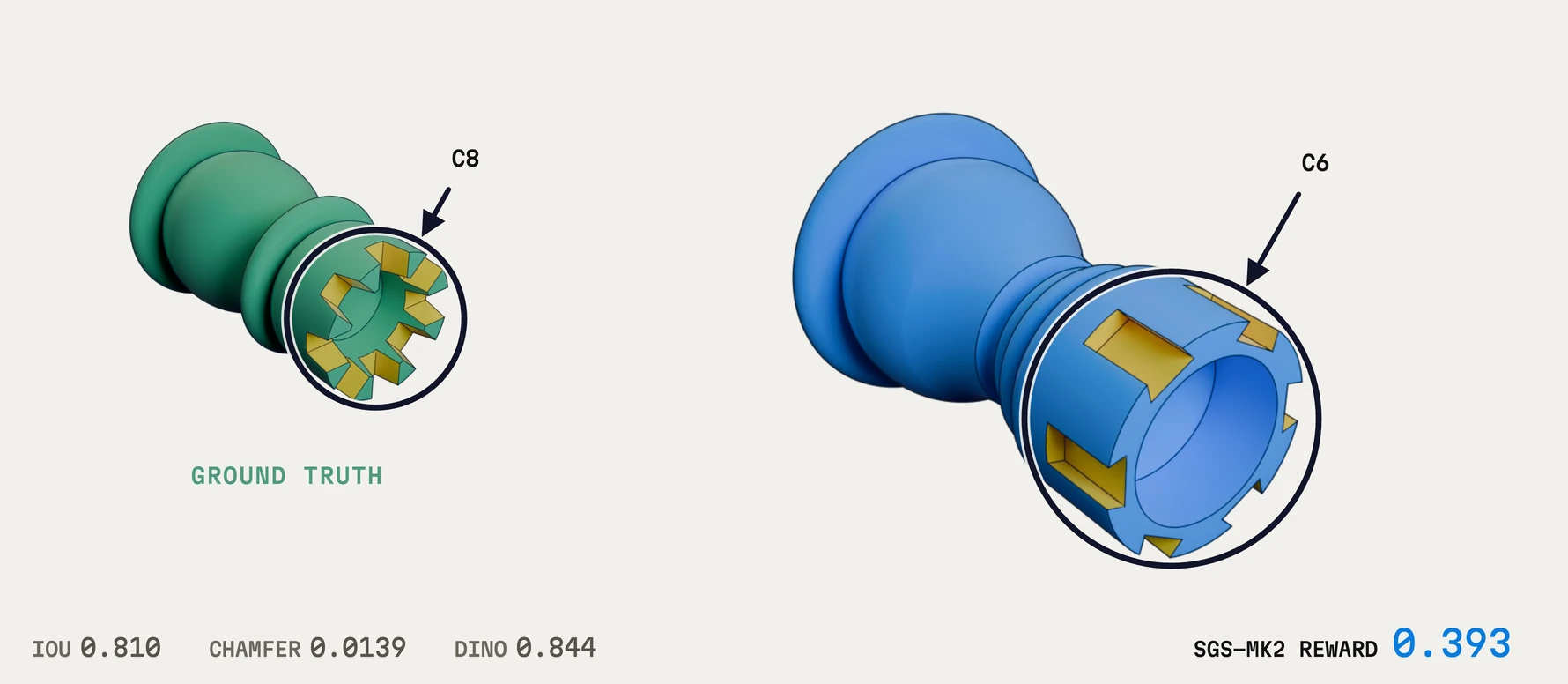
(a) Wrong pattern count. Six slots where the design has eight: low reward.
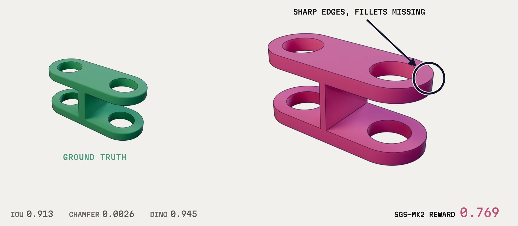
(b) Missing fillets. Right features, unfinished edges: partial credit.
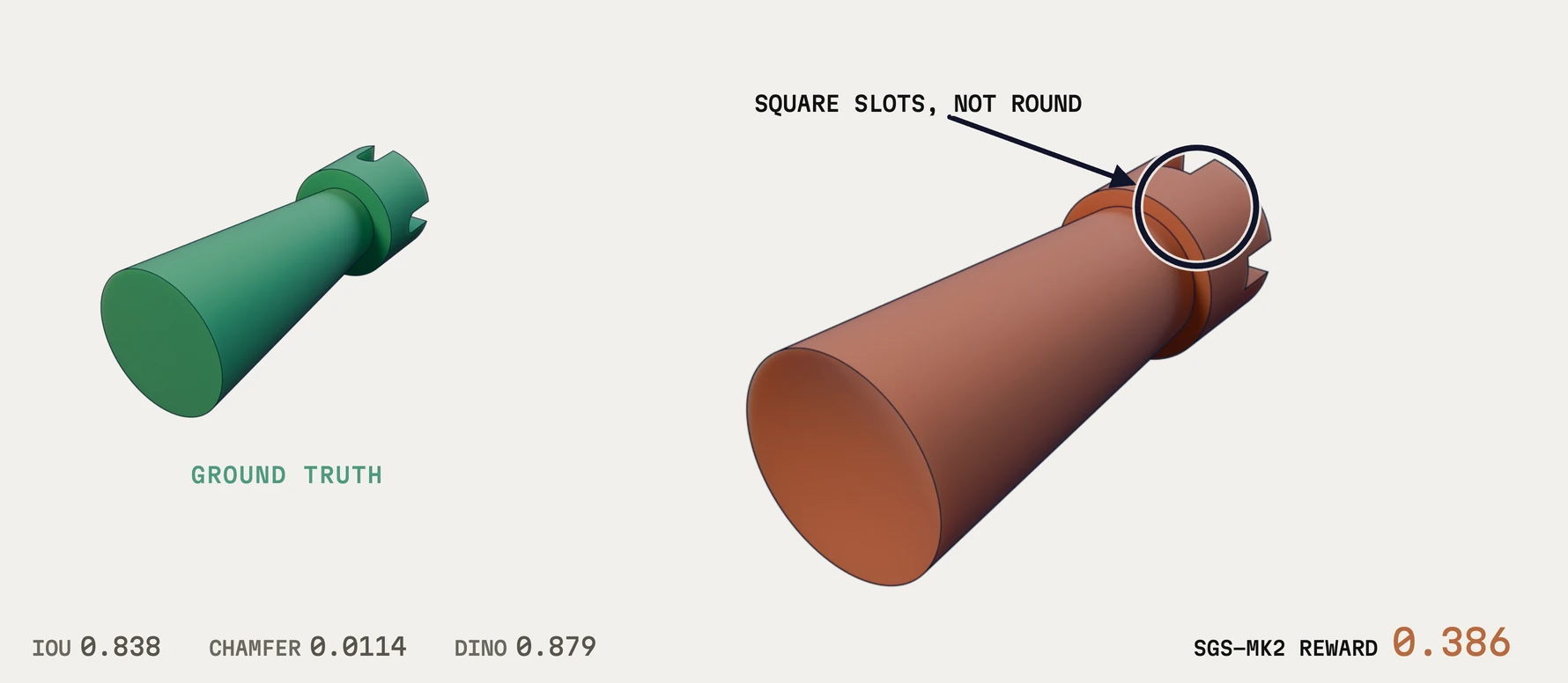
(c) Wrong slot shape. Square slots where round ones belong: low reward.
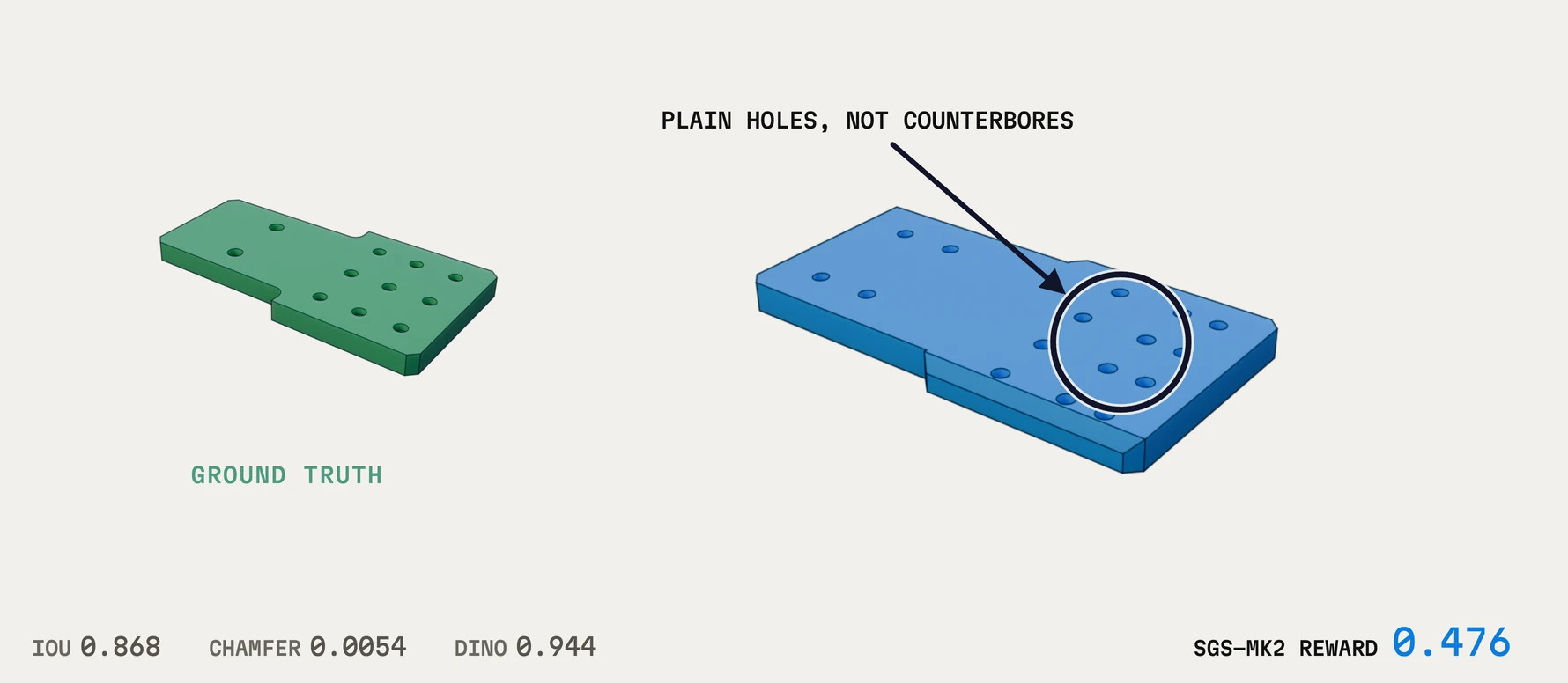
(d) Wrong hole type. Plain holes where counterbores belong, so bolts won’t sit flush: low reward.
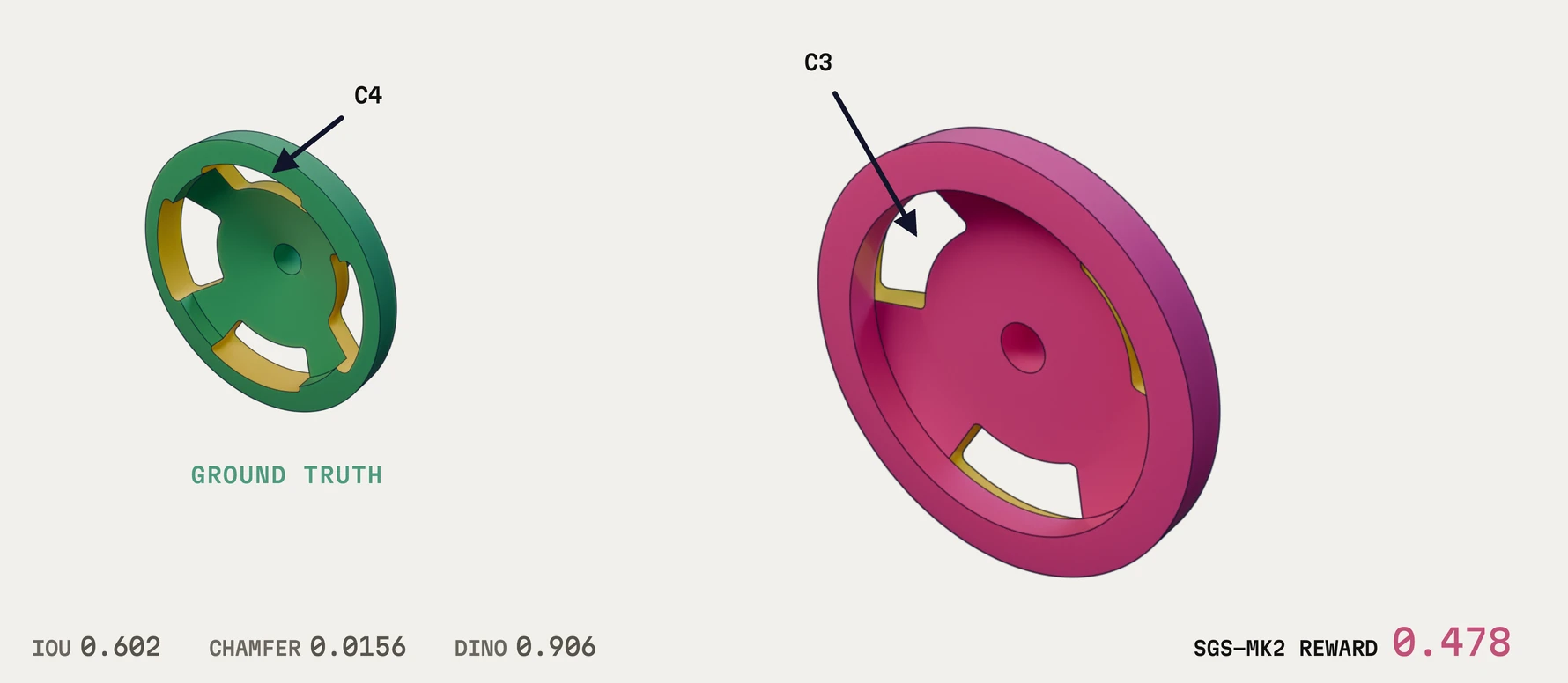
(e) Wrong cut-out pattern. Three cut-outs where the design has four: low reward.
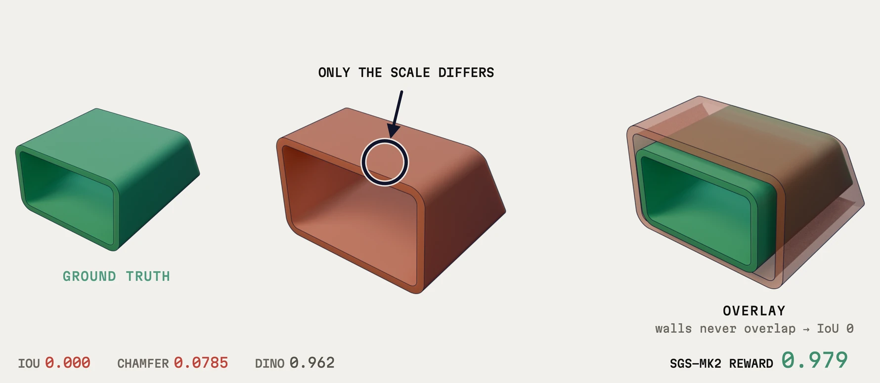
(f) One value off. Every feature right, only the scale differs: high reward. The thin walls never overlap, so IoU reads zero (overlay, right).
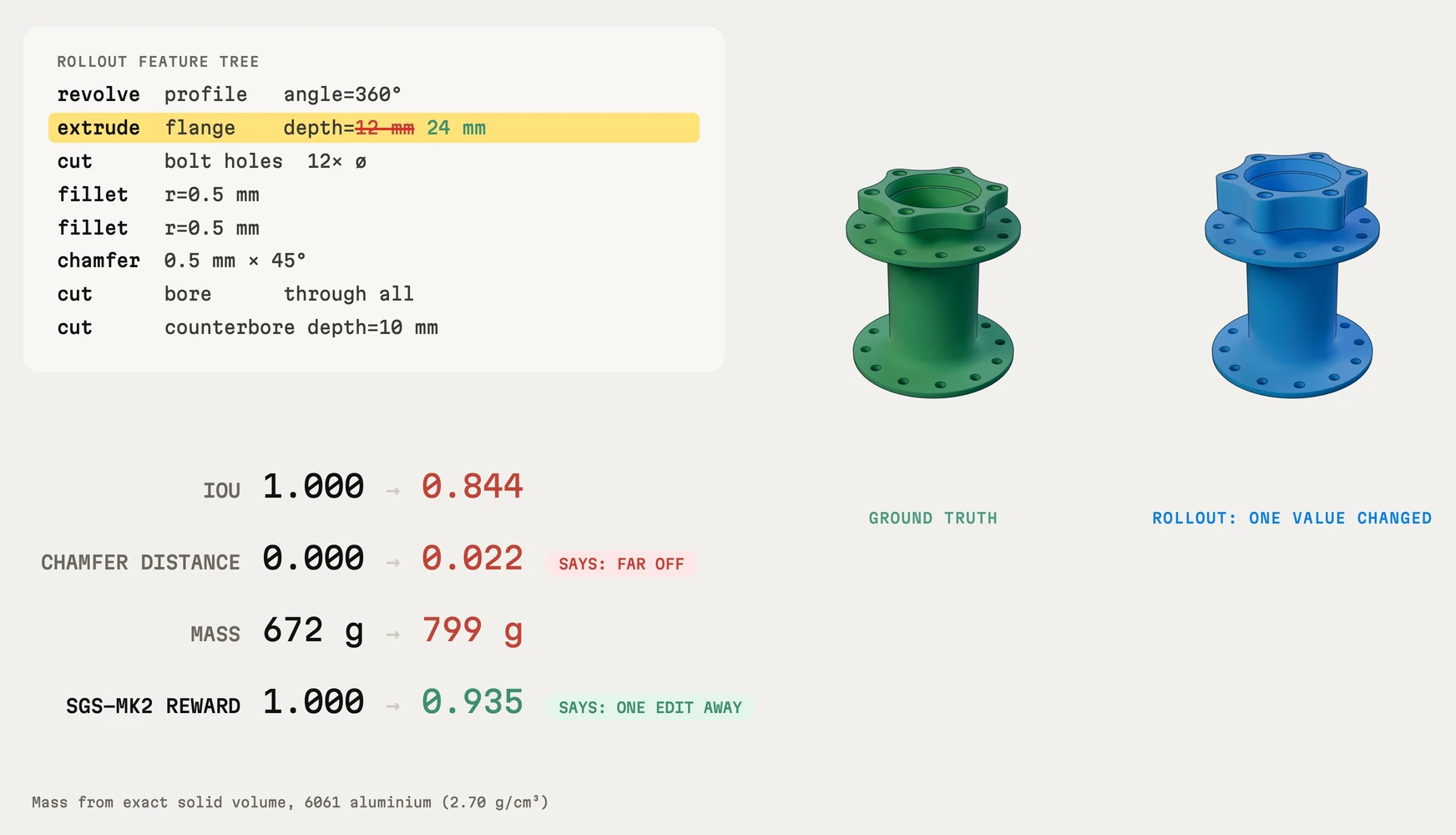
Where we go from here
None of the members of our team claims an individual certification as a SOLIDWORKS Professional as a result of having passed this exam with an agent. We are not in the business of cheating, nor are we interested in selling unauthorized exam aids.
Our team is obsessed with making it cheaper to produce real physical products which can perform practical tasks while operating safely and reliably. We are still in the early stages of that journey.
This result is a proof of concept and capability. We are now moving full speed toward manufacturability and CAD modeling in real engineering contexts, because that is what helps people build physical things, and build them with the assurance that they function as intended. Our target is end-to-end design automation and workflow optimization with our models (both our native geometry encoder and SGS-Mk2) in the loop. We have trained a CAD foundation model which is capable of reasoning symbolically about the geometry, topology, and kinematics of parts and assemblies. Our broader ambition is to scale these models and couple them tightly to both frontier model development and our harness environment, to reason over the full engineering state of a physical system: its geometry and interfaces, operating conditions, physics, manufacturing process, cost, supply chain, and field history.
From a technical perspective, an engineer should be able to express anything from a direct geometric change to a high-level objective: reconfigure a machine for a new customer, reduce delivery times and freight costs, improve serviceability, and have the system propagate that intent through assemblies, meshes and simulations, manufacturing plans, BOMs, and sourcing context. The challenge is to evaluate these consequences in parallel, in a tight feedback loop, and feed failures or tradeoffs back into the next design decision.
From a business perspective, existing CAD workflows are siloed, leaving money on the table for manufacturers. We aim to serve cost economics to our customers. Building a positive-sum CAD experience and a strong product with validated outputs is also a matter of ensuring design safety under cost reduction objectives. Our competitive advantage will be that we have built a fast, iterative engineering loop in which design, analysis, manufacturing, and real-world outcomes continuously inform one another while outputs which are consequential to production and operation remain both inspectable and verifiable. Building the harness, interoperability, and shared engineering context required to support that loop now becomes our focus. This means we are optimizing workflows which:
- Turn user intent into coordinated changes across parts, assemblies, kinematics, simulation, manufacturing, BOMs, and sourcing, rather than treating each as a separate workflow;
- Plug machine shops, manufacturers, asset management, and procurement seamlessly into the CAD loop; and
- Optimize designs against real production objectives using manufacturing constraints, supplier data, and field outcomes as feedback into the design process.
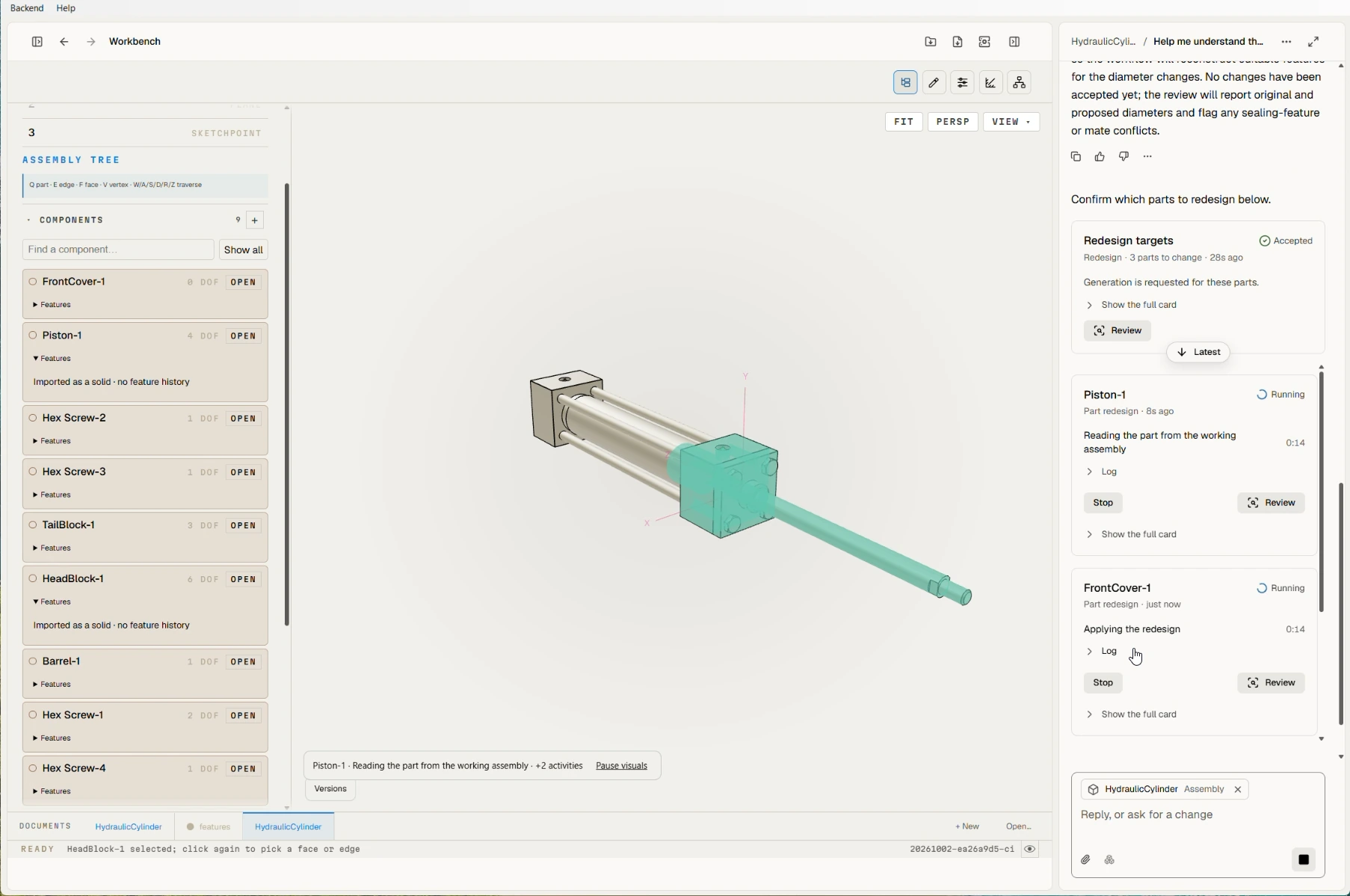
(a) Running. Three parts are confirmed for redesign, and the agent works on them in parallel.
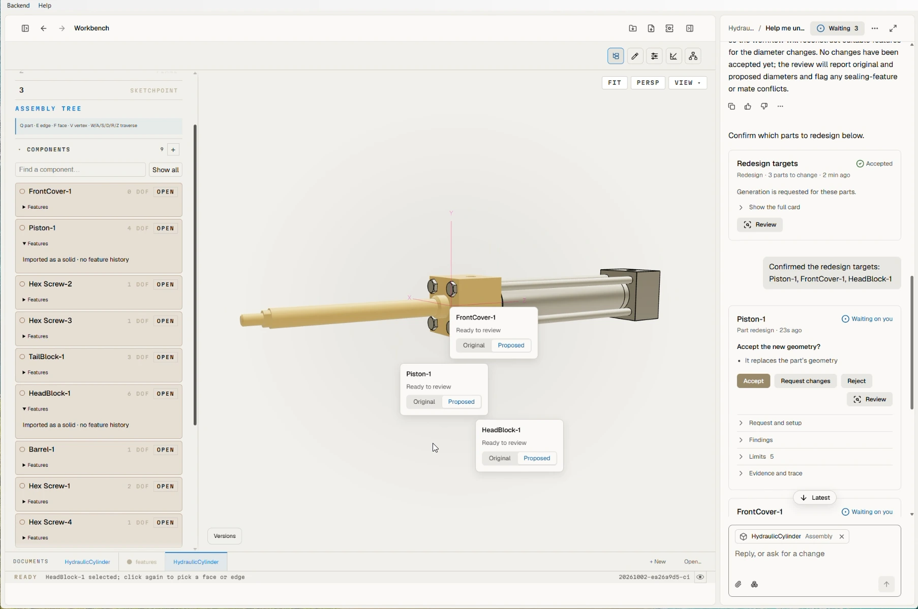
(b) Review. Each proposal can be easily compared against multiple versions, then accepted, revised or rejected.
This SOLIDWORKS Professional Certification benchmark acts as further validation of our research team’s capabilities and technical approach. From here, we will invest in the abstract reasoning of the SGS class of models by:
- Interleaving traditional constraint management methodologies with more modern techniques adapted from computational proof checking and satisfiability, with human-readable integration into the design process;
- Training on long time-horizon tasks which regress on not just simulated realistic, but genuinely physical and real-world signals of manufacturability, informed by in-house expert talent; and
- Engaging where possible with the broader public and scientific community to improve the interpretability, safety, and steerability of agentic CAD and DFM.
As a first step toward public research engagement, we are co-releasing with this announcement a spall: an anonymized, de-documented software container designed for use with open source frameworks, which permits the broader academic community a window into our work and an opportunity to engage with us scientifically as we build.
Notes
- aScreen recordings of people completing the full CSWP are available online, and computer-use agents may be trained on them now or in the future. This is one reason we ran these tests through Quartz’s CAD tools rather than through screen control: a model cannot pass by reproducing a sequence of clicks it has already seen.
- bSome exam questions need no geometric reasoning at all. Each segment, for example, opens with a question that awards 5 points for clicking “Yes”. We left these out of the comparison.
References
- [1]Cognition. Introducing Devin, the first AI software engineer. March 12, 2024.
- [2]Cognition. SWE-bench technical report. March 15, 2024.
- [3]OpenAI. GPT-4 Technical Report. arXiv:2303.08774, 2023.
- [4]Hacktron. Hacking OpenAI. September 13, 2026.
- [5]OpenAI. The Hugging Face incident and the road ahead. August 26, 2026.
- [6]E. Bengio, M. Jain, M. Korablyov, D. Precup, Y. Bengio. Flow Network based Generative Models for Non-Iterative Diverse Candidate Generation. NeurIPS, 2021.
- [7]Y. Bengio, S. Lahlou, T. Deleu, E. J. Hu, M. Tiwari, E. Bengio. GFlowNet Foundations. JMLR, 2023.
- [8]X. Chen, X. Han, J. Hu, F. J. R. Ruiz, L. Liu. Order Matters: Probabilistic Modeling of Node Sequence for Graph Generation. ICML, 2021.
- [9]P. Saini, A. Yu, H. Nazoordeen. CAD Arena. Normal Research.